What is an Electronic Breadboard
Understanding electronic breadboards is essential for anyone starting out in electronics projects.
An electronic breadboard, simply called a “breadboard,” is a reusable platform used for prototyping electronic circuits. Understand electronic breadboards allows engineers, hobbyists, and students to build and test circuit designs without the need for soldering components together.
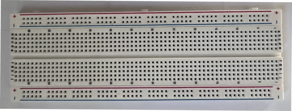
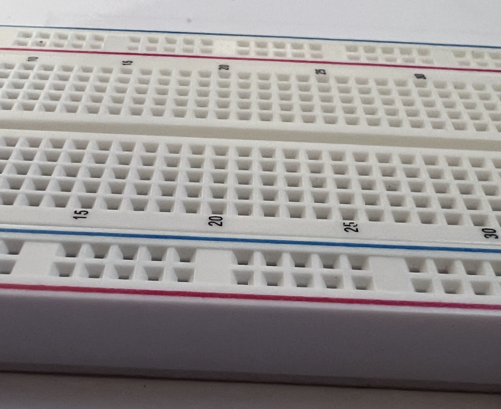
A typical breadboard consists of a plastic board containing a grid of holes. These holes are connected in a specific way allowing for easy insertion of components like resistors, capacitors, integrated circuit chips and wires. Understanding electronic breadboards helps individuals grasp how these connections are made.

Breadboard Layout
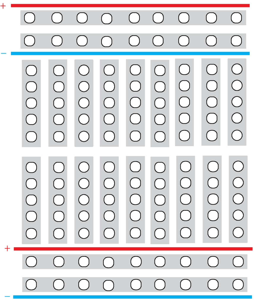
Most breadboards have power rails along the top and bottom, which are typically used for connecting power to the circuit. These rails are usually marked with red and blue lines to indicate positive and negative connections. The central area of the breadboard is divided into terminal strips, which are organized into rows and columns. These strips allow for connections between components by inserting their leads into the holes. The rows in the terminal strips are often connected horizontally in groups, while vertical connections are usually made by inserting components into the same column. Understanding electronic breadboards is crucial for making these connections accurately.

No Soldering Required
One of the biggest advantages of breadboards is that they allow for easy assembly and testing of circuits without soldering. This is particularly useful for prototyping.
Components can be easily removed and repositioned, allowing for many iterations of a design without any waste.
Overall, understanding electronic breadboards is essential for testing and developing new circuits before finalizing them in a more permanent form, such as a printed circuit board (PCB).
