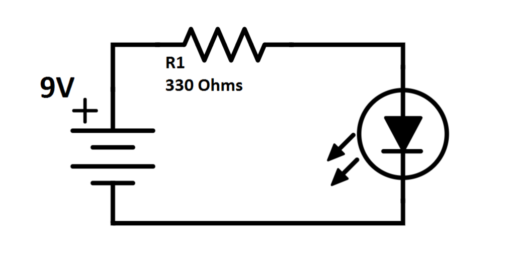
Electronic schematics are specialized diagrams that represent the components and connections in electronic circuits. They serve as a blueprint for designing, building, and troubleshooting electronic devices. Here’s an in-depth overview of electronic schematics:

Definition
A schematic diagram is a symbolic representation of an electronic circuit. It uses standardized symbols for various components and lines to represent the electrical connections between them.
Purpose
Design and Planning: Engineers and designers use schematics to plan and visualize how circuits will function.
Documentation: They serve as a permanent record of the circuit design, which can be referred to for maintenance, troubleshooting, and modifications.
Communication: Schematics facilitate communication among engineers, technicians, and manufacturers, providing a common language for discussing circuit design.
Electronic Schematics Symbols
Resistor

Capacitor

PNP Transistor

Potentiometer

Diode

NPN Transistor

Light Emitting Diode

Ground

Speaker

battery

Switch

AC Power Source

Fuse

Connected Wires

Crossing Wires

Types of Electronic Schematics
Basic Circuit Schematics: Simple representations showing fundamental circuits like resistive dividers, RC filters, or amplifiers.
Complex Circuit Schematics: These diagrams include multiple components, subsystems, and often incorporate various functional blocks, making them suitable for intricate systems like microcontroller circuits.
Block Diagrams: Higher-level diagrams that represent the major functional blocks of a system without detailing every connection or component.
Pictorial Schematics: Combine graphical images of components with schematic symbols, providing a more visual representation.
Wiring Diagrams: More detailed diagrams that show the physical layout of the wiring in a device, commonly used in automotive and industrial applications.
Reading Electronic Schematics
To effectively read and interpret electronic schematics, one should:
Familiarize with Symbols: Understand the basic symbols used for common components.
Trace Connections: Follow the lines to see how components are connected, identifying the flow of electricity.
Identify Power Sources: Locate where the power supply connects to the circuit and how it distributes power.
Analyze Functionality: Understand how components interact, including how they affect voltage, current, and overall circuit behavior.
Applications of Electronic Schematics
Consumer Electronics: Used in the design and documentation of devices like smartphones, tablets, and home appliances.
Industrial Automation: Employed in designing control systems for machinery, including PLC (Programmable Logic Controller) circuits.
Research and Development: Used in laboratories to design and test new electronic devices and systems.
Education: Schematics are essential teaching tools in electronics and engineering programs, helping students learn circuit design and analysis.
Best Practices
Consistent Symbol Use: Stick to standardized symbols to ensure clarity and comprehension.
Clear Labeling: Properly label all components and connections for easy identification.
Organized Layout: Keep the schematic neat and organized, avoiding crossing lines whenever possible.
Document Changes: If modifications are made, update the schematic to reflect the latest design accurately.
Conclusion
Electronic schematics are foundational tools in the field of electronics and electrical engineering. They provide a clear, standardized way to represent complex electrical systems, facilitating design, communication, and troubleshooting across various applications. Mastering the reading and creation of electronic schematics is essential for anyone involved in electronics, from hobbyists to professional engineers.
